exportIDFS is a program which is used to extract and export data that has been stored in the Instrument Description File System (IDFS) format. The IDFS format is a data storage format that is designed to be general enough to handle the majority of scientific data sets. These data sets include raw telemetry, processed data, simulation data and theoretical data. IDFS data sources are defined as either scalar instruments or vector instruments. A scalar instrument returns singular data quantities that are dependent only upon time and position. A vector instrument returns one-dimensional data quantities that have a functional dependence on a single variable, which in IDFS terminology is called the scanning variable.
The exportIDFS program can be invoked in one of two modes:
(1) interactive mode or (2) batch mode. In interactive mode, the program
utilizes a GUI-based definition session to define the data items to be
exported. Once this definition session has been completed, the selected data
parameters can then be exported to the selected file format. To invoke the
program in interactive mode, type exportIDFS at the command line.
In batch mode, the interactive GUI-based definition session is bypassed and
the data requested is immediately exported based upon information contained in
the named layout file. To invoke the program in batch mode, type
exportIDFS -FName filename at the command line. The argument
filename is the name of the layout file that is to be
utilized during the current export session. Note that the name of the
layout file does not include the .EXP extension, which is appended to the
filename provided by the user during the GUI-based definition session. If the
named layout file does not exist, an error is displayed and processing terminates.
For a complete list of arguments that can be utilized by SDDAS applications
that support batch mode processing, the user is referred to the
SDDAS Applications Batch Interface document.
The user should be aware that the exportIDFS program
utilizes only the layout filename, beginning time, ending time, graphics
device number and graphics output filename command line options.
If any of the other command line options are specified, a message is displayed
stating that the specified option is not utilized for the exporting of the data
for the current export session. The exportIDFS program utilizes
the graphics device number and the graphics output filename command line options
differently than the other SDDAS applications since there is no graphics output
associated with exportIDFS. The exportIDFS program
utilizes the graphics device number command line option to allow for the selection of
the file format to which the data is to be exported (CDF, netCDF, IDFS or XML).
The exportIDFS program utilizes the graphics output filename command
line option to specify the name of the file that will contain the data that is exported.
The recommended calling sequence omits any filename extension when
using the graphics output filename command line option. This allows the
exportIDFS program to append the correct output filename extension
based upon the file format selected. For example, if the layout file specifies that
the data is to be exported in netCDF format, then making the following call
exportIDFS -FName filename -OName NewData will place the data that is
exported into a file that is named NewData.nc.
The user is referred to the "Data Packaging" section
which explains the different data file formats which are outputted by the
exportIDFS program.

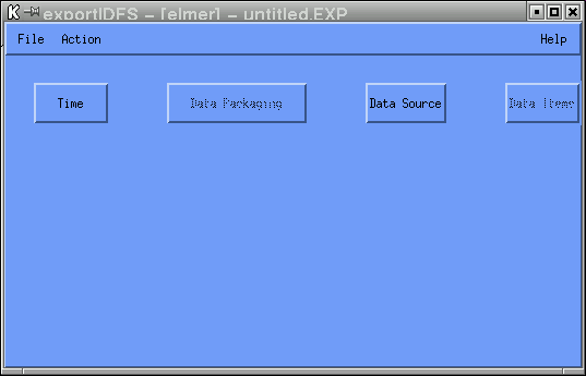
In order to export IDFS data, an IDFS source must first be selected. This is achieved by selecting the "Data Source" button. Once a valid IDFS source has been selected, the "Data Items" button becomes visible. At this point, the data items to be exported from the selected IDFS source must be defined. At least one data item must be selected; otherwise, an error message will be displayed when the "Export" action is selected.
In most cases, the data items to be exported are referred to as IDFS sensors. An IDFS sensor is defined as a primary data source returned by the virtual instrument in question. However, in some cases, the data items may be SCF output variables. The SCF (Science Computation Formulation) system provides for the creation of new data products from an existing primary data set (IDFS). In some cases, these derived products may be dependent upon values returned from a single instrument; in other cases, the derived products are dependent upon values taken from many instruments. For a more in-depth explanation of the SCF system, the user is referred to the paper entitled "The Science Computation Formulation System".
When the "Data Items" button is selected, the Data Sources GUI is displayed. On this GUI resides a list which indicates the data items to be exported. Initially, this list is empty. To add a data item to the list, the pull-down Insertion menu is utilized. Once the position for the data item to be added has been determined, the actual data item must be defined using the Data Attributes GUI. This GUI is automatically invoked when a new item is added to the list. The parameter selection is defaulted to the first data item defined for the IDFS source based upon information contained in the PIDF file. If changes to any of the attributes for a specific data item need to be made, the data item should be selected from the list and the "Attributes" button should be activated in order to invoke the Data Attributes GUI.
Once the data item has been selected, binning information must be provided for the data item. The binning information is defaulted based upon information contained in the PIDF file for the selected data item. For IDFS data items, all sensors are binned using the same binning scheme (FIXED_SWEEP vs. VARIABLE_SWEEP); therefore, the first data item definition on the list defines the binning scheme that will be used by all exported IDFS sensors. For SCF output variables, each data item is binned uniquely. Therefore, if three SCF output variables are selected for export, three unique binning schemes are utilized by the data acquisition software. The user need not concern themselves with this information unless a change in binning schemes is desired, which can be achieved by selecting the "Binning" button. The user must keep in mind that the Binning GUI is utilized by other applications besides exportIDFS and that not all options defined on the Binning GUI are applicable to the exportIDFS program. The exportIDFS program does not allow for the manipulation of the data buffers that are returned; therefore, the menu options which are pertinent to the data buffer manipulation for data gaps and missing data values within a data buffer are not utilized. These menu options are hidden from the user when the Binning GUI is displayed.
The exportIDFS program allows for the exportation of IDFS sensor or SCF output variable data, but not any combination of the two data sources. The first data item definition on the list determines if IDFS or SCF data products are to be exported. If both IDFS and SCF data items are needed, separate instances of the exportIDFS program must be run.
Once data items to be exported have been selected, the file format and averaging scheme for the data must be chosen. This is achieved by selecting the "Data Packaging" button. Currently, IDFS and SCF data can be exported to one of four file formats:
In addition to the file format, the user must also specify the averaging scheme to utilize for each exported data sample. The user may specify either a sample average or a time average. With a sample average, the user specifies the number of data samples (sweeps) to average together for each exported data sample. With a time average, the user specifies the amount of time to be acquired for each exported data sample. When time average is selected, the time specified is converted to sweeps using the maximum temporal resolution allowed by the selected virtual instrument. If the result is a non-integer value, the number of sweeps acquired is determined by adding the integer component with the ceiling of the accumulation of the fractional component. If no averaging is required, that is, if a sweep by sweep dump is to be performed, a sample average with number of samples set to one should be defined. This is the default scenario for the exportIDFS program.
Before the exportIDFS program can export the data, one final piece of information must be defined. This information is the time range for which the data is to be acquired. This is achieved by selecting the "Time" button.
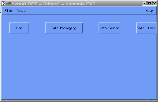
Once the IDFS source, data items, file format and time range have been defined, the selected data items can then be exported to the selected file format. To export the data, select the pull-down Action menu from the main menubar and select the Export option. Upon activation, the local database is checked to see if the requested data files are online. If data for the requested time range is not online, the missing data is promoted to the local disk. Once the data has been placed online, the datafiles are opened, the data is extracted and exported to the selected file format. Data will continue to be processed until the user-requested end time has been reached or until an error condition is raised. When an error condition is encountered, a message is displayed, the partially created file is purged and processing terminates. Upon completion of the export task, successful or unsuccessful, any promoted IDFS data files are removed from the local disk.
When the exportIDFS program is run in interactive mode, a check is made to see if the file to be generated already exists in the current working directory. If it does, the user will be asked if they wish to overwrite the data file. If the user answers yes, the file is removed and an attempt is made to create a new file. If the user answers no, the current request for data exportation is aborted. When run in batch mode, no query is made; the file is removed and an attempt is made to create a new file.
Since the exportIDFS program has the potential to generate large data files, a clean-up mechanism is utilized. Whether or not the clean-up mechanism is invoked depends upon the actual user running the exportIDFS program. If there exists a ".guest" file in the user's home directory, the data file will be scheduled for removal 30 minutes after the data file has been closed. The user will be informed of this situation. If a ".guest" file does not exist in the user's home directory, the generated data files will be left untouched. This scheme was designed for those sites that set up a public guest account through which outside users are given access to the named local system. The contents of the ".guest" file is not important; simply, the existence of the file is utilized.
For IDFS sensor data, the exportIDFS program will export the selected data items, data quality information, any secondary data sources selected for exportation and the time range associated with each data sample. If the IDFS source returns instrument status values, this information is also exported. Instrument status values utilize a separate time tag, which will be written to the file. All of this information is considered record-variant since the values change from data sample to data sample. If the selected IDFS source is a vector-instrument, the scan values which correspond to the returned data bins are written to the file. The center scan values and the band-width values for each data bin are written once to the file since these values remain constant. However, there may be one set of scan values to be utilized by all selected data items or there may be a set of scan values per selected data item, based upon the information that is defined for the virtual instrument selected and the binning scheme that is selected.
For SCF output variables, the exportIDFS program will export the selected data items along with the time range associated with each data sample. This information is considered record-variant since the values change from data sample to data sample. If the SCF output variable returns non-scalar data, the scan values which correspond to the returned data bins are written to the file. The center scan values and the band-width values for each data bin are written once to the file since these values remain constant. Unlike IDFS sensors. each SCF output variable can bin data uniquely. Therefore, if three non-scalar SCF output variables are selected for export, three unique binning schemes are utilized by the data acquisition software and thus, three sets of center and band-width values are written to the file.
Once all the information has been defined, the information may be saved to a layout file for future retrieval. This is achieved by selecting the pull-down File menu and selecting the Save As option. The information defined is not saved by the program unless the user explicitly does so. Note that when providing the name of the layout file, do not specify the .EXP extension. The exportIDFS program automatically appends the .EXP extension to the name of the layout file upon creation of the file.
Due to the limitations / restrictions of the various formats, the following conventions are followed:
Instrument status values, or MODE data, are pertinent to the instrument as a whole, not to any one sensor definition. For netCDF, the naming convention utilized for the instrument status values is MODEx, where x represents the mode definition number, starting with zero. This convention was selected since a mapping variable is provided for each instrument status value defined. This mapping variable is an array of ASCII strings that describe what the value for the mode represents. There should be one definition for each possible value for the mode (3 bits = 8 definitions). For example, MODE1 is a status value defined to have two states - 0 and 1. There is also a mapping variable called MODE1_key, which has 2 entries, "Low Bias" and "High Bias". Therefore, when MODE1 returns a value of 0, the instrument is in Low Bias mode. It was decided that it would be easier to match numbers than it would be to match names since the user would first have to determine what the names were for each of the instrument status values.
For CDF, the naming convention utilized for the instrument status values is MODEx_descriptive name, where x represents the mode definition number, starting with zero. This convention was selected since a mapping global attribute is provided for each instrument status value defined. This mapping variable is an array of ASCII strings that describe what the value for the mode represents. There should be one definition for each possible value for the mode (3 bits = 8 definitions). For example, "MODE1_Retard Sweep Range" is the second status value (MODE1) defined for the IDFS data source of interest. The name defined for this instrument status value is "Retard Sweep Range". This instrument status value has two defined states - 0 and 1. There is also a mapping variable called "MODE1_KEY", which has 2 entries, "Low Bias" and "High Bias". Therefore, when "MODE1_Retard Sweep Range" returns a value of 0, the instrument is in Low Bias mode. It was decided that it would be easier to match numbers (MODEx_) than it would be to match names since the user would first have to determine what the names were for each of the instrument status values.
All of the data blocks identified above may or may not be contained within the XML file created, based upon the IDFS data source selected. For scalar IDFS data sources, there is no scan information; therefore, the Scan Block information is not pertinent and is not included in the XML file generated. If the selected IDFS data source has a scan variable associated with it, the Scan Block information is included in the XML file generated and a Scan Index value is placed within the Sensor block to link the data with the scan information. There will either be one scan block defined, which all data sources utilize or there will be one scan block defined for each IDFS data source selected. If the IDFS data source does not define any data quality or instrument status values in the PIDF file, there is no Data Quality or Mode information to be written to the XML file. The Pitch Angle, Start Azimuthal Angle, Stop Azimuthal Angle and Calibration blocks pertain to secondary data sources and therefore are written to the XML file if the secondary data source is applicable for the selected IDFS data source and if the user selected the secondary data source for exportation.
When the user selects XML as the file format for SCF data items, the file generated is simply an ASCII file which contains the selected SCF data parameters, all identified using XML tags. The data is basically blocked or grouped together in the following manner:
All of the data blocks identified above may or may not be contained within the XML file created, based upon the SCF output variables selected. Unlike IDFS data sources which are uniform in rank, SCF output variables can be a mixture of scalar and multi-dimensional data (1-D up to 10-D). If the selected SCF output variable has a scan variable associated with it, the Scan Block information is included in the XML file generated and a Scan Index value is placed within the Data Item block to link the data with the scan information. This is done for each SCF output variable that has scan information defined; therefore, there may be multiple Scan Blocks contained within the XML file.
The following table identifies the tags which are utilized by the exportIDFS program for the XML file format option:
| XML Tag | Pertinent to IDFS or SCF |
Meaning |
|---|---|---|
| Idfs_Parameters | IDFS | token which identifies the data as IDFS data items(s) |
| Scf_Parameters | SCF | token which identifies the data as SCF output variable(s) |
| Scan | IDFS and SCF | token which groups together information that is associated with the scan variable for the data items(s) being exported |
| Scan_Unit | IDFS and SCF | token which describes the units that the values are expressed in for the scan variable |
| Scan_Length | IDFS and SCF | token which defines the number of values returned for the scan variable |
| Center_Scan | IDFS and SCF | token which identifies the center scan values associated with the data items being exported |
| Scan_Low | IDFS and SCF | token which identifies the lower scan edge values for the scan range associated with the data items being exported |
| Scan_High | IDFS and SCF | token which identifies the upper scan edge values for the scan range associated with the data items being exported |
| Scan_Block_Index | IDFS and SCF | token which represents a scan block identifier number. This number is used to link the exported data parameters with any scan information pertinent to the data item in question. |
| Data_Set | IDFS and SCF | token which groups together information that is associated with each exported data sample |
| Number | IDFS and SCF | the exported data sample number, with numbering starting at zero (like a record counter) |
| Start_Time | IDFS and SCF | token which defines the start time for the exported data sample |
| Stop_Time | IDFS and SCF | token which defines the stop time for the exported data sample |
| Data_Item | SCF | token which groups together information that pertains to each selected SCF output variable |
| Scan_Index | IDFS and SCF | token which represents an index value (link) to the scan block information that is pertinent to the IDFS sensor named in the Sensor block or to the SCF output variable named in the Data_Item block in which the token appears |
| Sensor | IDFS | token which groups together information that pertains to each selected IDFS data item |
| Data_Quality | IDFS | token which identifies the data as the data quality value associated with the Sensor named in the Sensor block in which the token appears |
| Start_Azimuthal_Angle | IDFS | token which identifies the data as the start azimuthal angle data associated with the Sensor named in the Sensor block in which the token appears. The start azimuthal angle values are always returned as values between 0 and 360 degrees. |
| Stop_Azimuthal_Angle | IDFS | token which identifies the data as the stop azimuthal angle data associated with the Sensor named in the Sensor block in which the token appears. The stop azimuthal angle values could be negative or could be greater than 360 degrees. The stop azimuthal angle values are computed by adding the degrees covered by the accumulation time of each sample to the start azimuthal angle values. |
| Pitch_Angle | IDFS | token which identifies the data as the pitch angle data associated with the Sensor named in the Sensor block in which the token appears |
| Calibration | IDFS | token which identifies the data as the calibration data associated with the Sensor named in the Sensor block in which the token appears. Unlike Data_Quality, Start_Azimuthal_Angle, Stop_Azimuthal_Angle, and Pitch_Angle, there will be one Calibration block defined for each calibration data set defined for the virtual instrument (IDFS data source) in question. |
| Mode_Start_Time | IDFS | token which defines the start time for the instrument status data associated with the exported data sample |
| Mode_Stop_Time | IDFS | token which defines the stop time for the instrument status data associated with the exported data sample |
| Mode | IDFS | token which identifies the data as the instrument status or mode data. The instrument status data is defined for the virtual instrument (IDFS data source) in question; therefore, this data type is not associated with any particular sensor. |
| Name | IDFS and SCF | token which identifies or gives a name to the data parameter being exported |
| Unit | IDFS and SCF | token which describes the units that the data values are expressed in for the data parameter being exported |
| Data_Length | IDFS and SCF | token which defines the number of data values returned for the data parameter being exported |
| Values | IDFS and SCF | token which identifies the actual data values that are being returned for the data parameter being exported |
Two XSLT stylesheets have been developed as examples in extracting the data from the xml formatted file. Both examples generate html code to display the data in tabularized format. The first stylesheet entitled IDFS.xsl can be used to process exported IDFS sensor data. The second stylesheet entitled SCF.xsl can be used to process exported SCF output variables.
To test these two stylesheets, an XSLT processor was needed. The principal role of an XSLT processor is to apply an XSLT stylesheet to an XML source file and produce a result "document". The XSLT processor utilized for the testing of the stylesheets was Saxon. Saxon is an open source XSLT processor developed by Michael Kay. It is a Java application, and can be run directly from the command prompt; no web server or browser is required. The html source generated by the stylesheets created is simply directed to standard out by Saxon. At the command line, standard output was re-directed to a file and that file was viewed through a browser for validation. The user is referred to the write-up for Instant Saxon for more information on this XSLT processor.
The remainder of this document gives an in-depth explanation of the options that appear on the various GUIs utilized by the exportIDFS program.
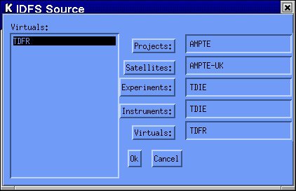
The user must select a project, satellite, experiment, instrument and virtual instrument from which data is to be extracted and exported. To change any of the selected options, click on the buttons on the right hand side. Note that all lineage information under the branch being changed is no longer applicable and must be re-selected. When the IDFS data source is changed, any previous data item definitions are deleted from the list and must be re-defined.
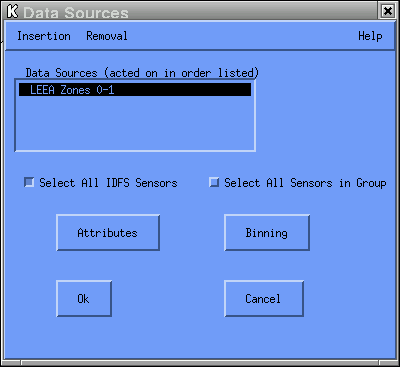
To add a data item to the list, the pull-down Insertion menu is utilized. The menu options indicate the position within the list at which the current data item definition is to be inserted. These options include:
To delete a data item from the list, the pull-down Removal menu is utilized. Currently, this pull-down menu contains just one option
The Select All IDFS Sensors check box applies only to IDFS sensors, not to SCF output variables. If SCF output variables are exported, this option is simply ignored. This option enables the user to export all IDFS sensors without having to individually add each data item to the list. If this check box is selected, only one data item may reside on the data list. When the data is actually exported, all IDFS sensors will be exported. using the same data unit number and the same scan unit number. The same set of ancillary data is processed for all sensors.
The Select All Sensors in Group check box applies only to IDFS sensors, not to SCF output variables. If SCF output variables are exported, this option is simply ignored. This option enables the user to export all IDFS sensors that belong to the same PIDF group without having to individually add each data item to the list. If this check box is selected, only one data item may reside on the data list. When the data is actually exported, all IDFS sensors that belong to the same PIDF group will be exported. using the same data unit number and the same scan unit number. The same set of ancillary data is processed for all sensors.
The "Attributes" button invokes the Data Attributes GUI. The "Binning" button invokes the Bins GUI.
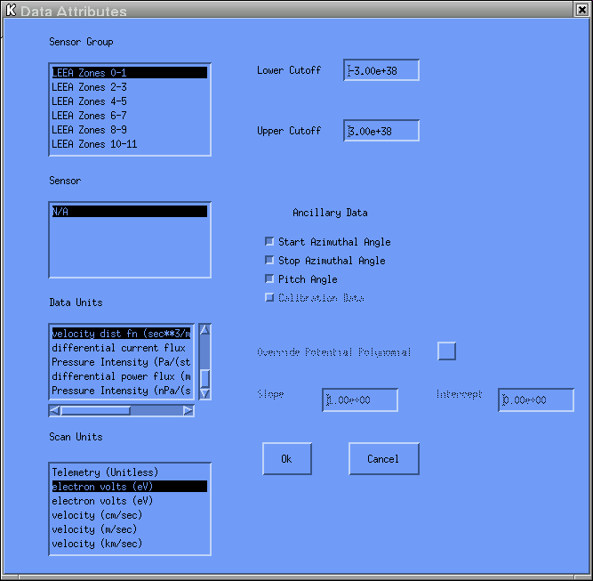
The primary data sources returned by the selected IDFS source are presented in two lists entitled Sensor Group and Sensor. The PIDF file utilizes these two groupings to allow an additional level of subdivision within the primary data sources. This scheme is useful when the IDFS source contains a large number of primary data sources representing a diverse set of measurements.
In some cases, there may be only one data unit defined. In other cases, a list
of data units will be presented. In either case, the Data Units
option is defaulted to the last data unit defined for the selected data item.
Data quality flags and the variables which describe the instrument state
are automatically exported, if the PIDF defines these data parameters.
Based upon the IDFS source selected, the last three items listed may or
may not apply. If they do apply, the user can select any or all of these
items for exportation. The default is set so that none of these last three
secondary data sources are returned; in other words, the user must "check"
the box in order to include these secondary data sources in the current
export session.
Note: if the file format to which the data is to be exported is IDFS,
ancillary data will only be exported for the ASCII Number Format,
as described above. Ancillary data will not exported for the TABULAR
Number Format, despite the selections made for this menu option.
If the IDFS data source selected uses spacecraft potential data in the conversion of the
values selected for the Data Units and / or the Scan Units
options, this menu option will become visible and may be changed from the default value
of "No" by the user.
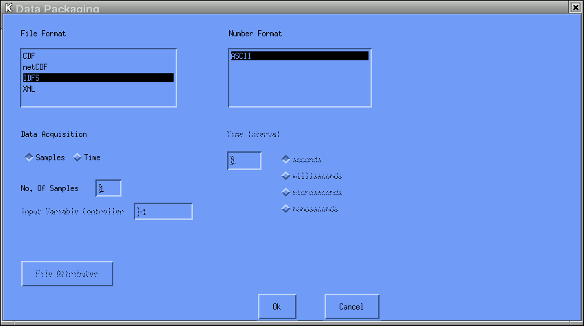
When a file is exported to the CDF file format, a file with a ".cdf" extension is created. When a file is exported to the netCDF file format, a file with a ".nc" extension is created. When a file is exported to the XML file format, a file with a ".xml" extension is created. The IDFS file format is simply an ASCII file which contains the selected data parameters. The extension that is appended to the file is based upon the option selected for the Number Format. If the ASCII option is selected, a file with a ".idfs" extension is created. If the TABULAR option is selected, a file with a ".txt" extension is created.
Rather than allow a growing list of ASCII file formats, it was decided to grow the Number Format list, where each option represented a unique way in which the ASCII data is to be presented within the output file. The default option (ASCII) represents the way in which IDFS data was written as ASCII output when the exportIDFS program was first developed. The file contains the selected IDFS data items, along with data quality information, secondary data sources and any instrument status values. The layout of the file is such that for each sweep of data, timetags are reported, the selected IDFS data item (sensor data) is outputted, followed by the Data Quality value and other secondary data products associated with the selected IDFS data item. This pattern of sensor data, data quality and secondary data is repeated for each selected IDFS data item. The instrument status values are then written, as they pertain to the instrument as a whole. In addition, there are variables reported to indicate the number of selected IDFS data items, the number of calibration sets defined and the number of instrument status values defined in order to process the data in a self-describing way. For SCF output variables, the layout of the file is such that for each sweep of data, timetags are reported along with the selected SCF data item(s).
For the TABULAR Number Format option, the file contains only the selected IDFS data items and any associated scan values. Unlike the ASCII option which places the scan values once at the beginning of the file, the TABULAR option places the scan values along with the sensor data for each row that is outputted. If all selected IDFS data items utilize the same scan values, the scan values are written once per row, after the time tags, followed by all the data items. However, if all selected IDFS data items do not utilize the same scan values, then the pattern "scan vector data vector" is repeated for each selected data item, after the time tags. There is a header that appears in Row 1 of the outputted file which contains the names of each item that is outputted along each row.
Data Acquisition - defines the averaging scheme used for each exported data sample.
Time - the user specifies the amount of time used to average the data for each exported data sample.
No. Of Samples - defines the number of data samples (sweeps) to average together for each exported data sample.
Input Variable Controller - defines which input variable to use when determining the amount of time to be processed for each iteration of the SCF algorithm.
Time Interval - the amount of time to be acquired for each exported data sample.
This widget is only displayed if the user selected Time as
the Data Acquisition option. The value can be expressed in one
of four time units:
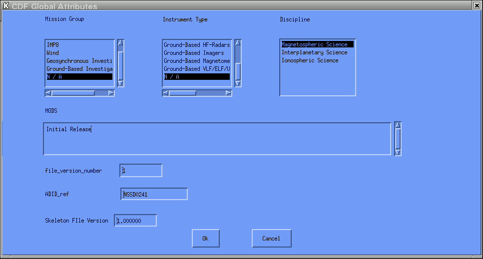
When the CDF file format is selected, a CDF file is created which contains the requested data items and meta data. The meta data is comprised of global-scope attributes that provide information about the data set as an entity. Some of the required global attributes have been selected for potential modification by the user. The values for these global-scope attributes are defaulted by the exportIDFS program. The user need not concern themselves with this information unless a change in the meta data is desired. A brief explanation of the options is given below. In all cases where a list is utilized, the list of options that are selectable are defined according to CDF documentation.

In order to set the time values, enter the values in the boxes that appear next to the time component being set or use the increment / decrement arrows. The stop time must be greater than the start time. The time is initially set to the current time. By Julian convention, January 1 is day 1.
Currently, this pull-down menu contains just one option
When this option is selected, the exportIDFS program exports the selected IDFS data items or SCF output variables for the selected time range.